No password is required to access these menu.
1.Main Page
2.Status Report
3.Old Report
4.Order Report
5.Performance Report
6.Group & Utility Report
7.Minute Report
You Need admin password to access these menu.
8.Admin Password
9.Setup Sensor
10.Setup Order
11.Setup Operator
12.Setup Utility Group
13.System Parameters
14.Setup Key Word
15.Setup Report
16.Backup Data
You Need user password to access these menu.
17.User password
18.Assign Order to Machine
19.Assign Operator to Machine
20.Batch and Order Management
Important Links to data if you wish to further process data in your system.
Raw data received from sensor.
Processed data.
Processed data parameter list.
Last hour report in CSV format.
Last shift report in CSV format.
Last day report in CSV format.
Last month report in CSV format.
Current hour minute report in raw format..
Reset channel of sensor.
Main Page - Since you can see this page, you have successfully established net connection to Web Interface Unit. The top bar is a menu bar. All the menu are accessible from here.
Status report - It will show you a condensed form of report on single page. The report has 80 boxes, each one representing a machine. The top text in box is machine number and bottom text is production, which can be selected in Setup report menu. The colour of box will tell you the status of machine as under.
Green - Machine is on and production is on.
Yellow - Machine is on, but production is stopped.
Red - The machine is off and there is no communication with sensor.
Grey - The Sensor is disabled, as there was no communication with sensor.
Old Reports -The Web Interface Unit will save 64 reports in all categories of hour, shift, day and month. You can view these reports to find the problem with machine.
Order Report -If you have set order data and assigned to machines then you can see the order reports. It will give you complete status of the order. If you have used batch management then, you will get order details batch wise also.
Performance Report -The performance report will give you performance of machine and operator, based on hour, shift, day and month reports.
Group & Utility Report -The Group and Utility report will give you production and other data of group of machines, based on hour, shift, day and month reports.
Minute Report - You can view production data minute by minute for a particular hour in current day. Please note that this data will be available for current day only.
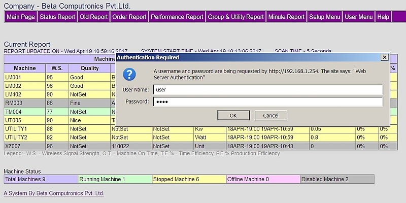
Setup Menu -This will give access to all setting related to system performance. You will need admin password to access this menu. The user name is admin and for password refer printed copy of manual.
User Menu -This will give access to all operational management. You can assigns machine to operator and order. It also provided order and batch management. You will need user password to access this menu. The user name is user and for password, refer printed copy of manual.
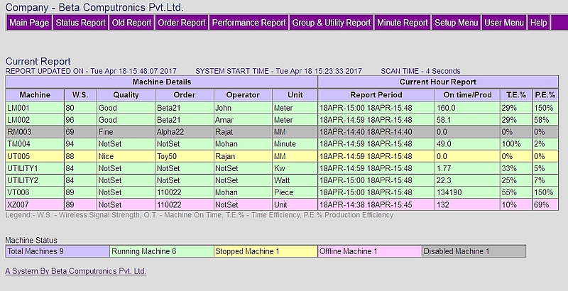
Below the menu bar you will see complete reports of the all machine. You can select the type (hour, shift, day or month) of report to be displayed in Setup report menu.
Machine -This is a given machine name, and set during the installation of sensor in Setup Sensor menu. This name should be unique and can not be repeated.
W.S. - This shows the wireless signal strength of sensor. Higher the value, sensor will be near the Web Interface Unit, and lower the value sensor is away from Web Interface unit.
Quality - This field can be used by user to show the type of product. This can be set in Order menu. It will be displayed as it is, but maximum character permitted is 8.
Order - If you have assigned any order to machine, the order number will be shown here.
Operator - If you have assigned operator to machine, the name will be shown here. The operator name will change automatically, when shift changes.
Unit - This is measuring unit, as set in Setup Sensor menu.
Report Period - This is the start and end time of report. If you find any discrepancy in production, efficiency then report period will help you to find the discrepancy.
Production - This is the production during the report period (hour, shift, day and month).
T.E % - This time efficiency calculated on machine on time and machine off time. When sensor is off line or disabled, then accuracy of this value is not correct.
P.E % - This is production efficiency. To get the correct efficiency you will have to enter target production in Assign Order to machine menu.
The main report has one row per machine. The colour of row will show you the status of machine as under.
Green - Machine is on and production is on.
Yellow - Machine is on, but production is stopped.
Red - The machine is off and there is communication with sensor.
Grey - The Sensor is disabled, as there was no communication with sensor.
Important Tips
1. If you are not interested in actual production value, but only status of machine, switch to Status Report.
2. Time efficiency and Production efficiency are important factors. Normally both value should be same and near 100%
3. If both efficiencies are low, then machine was not run to full capacity and indicate some break down.
4. If Time efficiency is high and Production efficiency is low, then machine was switched off or machine was run at low speed.
5. If Time efficiency is low and Production efficiency is high, then machine was run at high speed, or there is some tempering with sensor.
The Status report is a condensed form of report, where status of all machine is shown on one page.

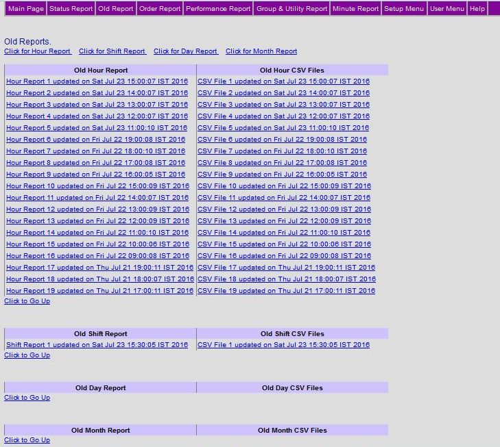
The Web Interface Unit will save 64 reports in all categories of hour, shift, day and month. These reports are also available in CSV format, which can be opened in excel sheet.
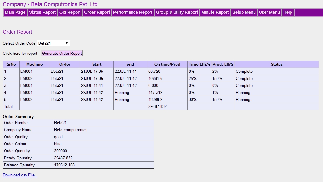
If you have set order data and assigned to machines then you can see the order reports. It will give you complete status of the order. If you have used batch management then, you will get order details batch wise also.
The performance report will give you performance of machine and operator, based on hour, shift, day and month reports.
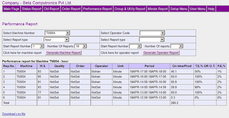
The Group and Utility report will give you production and other data of group of machines, based on hour, shift, day and month reports.
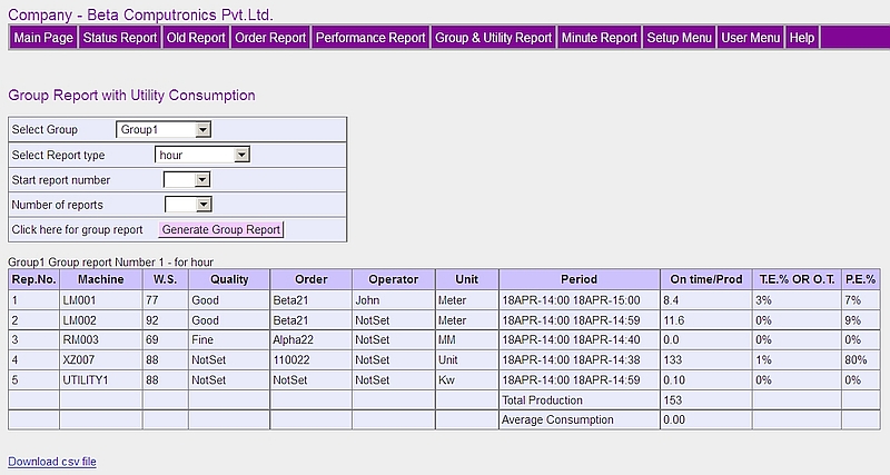
You can view production data minute by minute for a particular hour in current day. This data will be available for current day only.
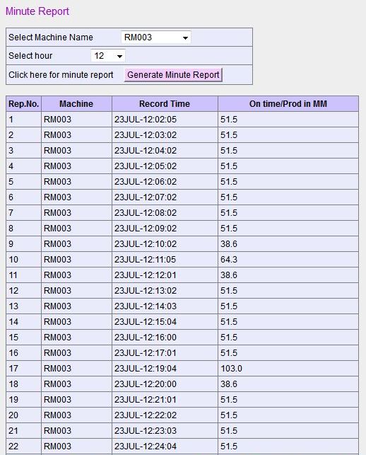
The system has two user namely admin and user. The admin can change all the parameter and settings, and user can change few parameters, which are not critical to system. So be very careful, when you log in as admin user. The password for admin and user are provided in manual. These passwords can be changed in system menu, and reset if required.
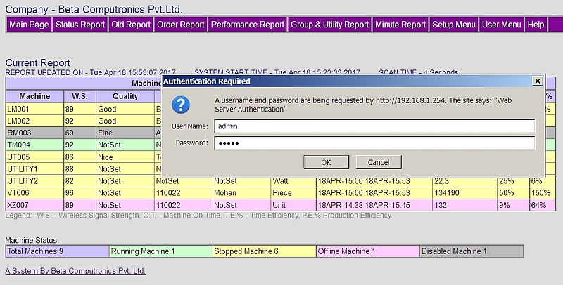
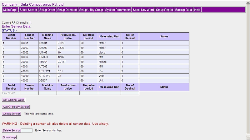
This is very important menu. You need to setup sensor accurately. Any mistake here will give you garbage reports. Please play attention to production per pulse.
PLEASE READ FOLLOWING BEFORE ENTERING THE DATA.
Please follow limiting values of the data you enter here. If you leave a field blank, default value will be saved. This menu is very important, and required for functioning of the system.
SENSOR NUMBER. - The sensor numbers are printed on the sensor. The number is programmed in sensor and can not be changed. By default all new sensor, will have not have any fixed channel. The channel will be programed when sensor is first time connected to Web Interface unit.
MACHINE NAME. - The machine name can be up to 8 characters consisting numbers and characters. This will be unique number and can not be repeated. You can choose the machine name according to your convention. If you have utility measuring sensor like KWh or Flow, name it as UTILITY1 to UTILITY5, so that you can group machines associated with that utility.
PRODUCTION PER PULSE. - Production per pulse should be more than 0 and less than 2000. You can use decimal value also. Please refer below for calculation of production per pulse.
NO PULSE PERIOD. - No pulse period is in second and range is 1 to 240 sec. When sensor does not receive a production pulse, a counter is started in sensor. If the counter value exceeds the no pulse period, it is assumed that machine is stopped and will be flagged in main page as yellow color.
MEASURING UNIT. - The name of measuring unit will depend on the production per pulse calculation. It can be maximum 7 characters.
NO. OF DECIMAL. - The number of decimal point is used if you want more precise production calculation. You can set maximum decimal to 3 positions, setting this value to 0 will round the production to integer.
STATUS. - The status column will show the sensor status. If sensor is enabled, then it will be scanned by Web Interface Unit and if disabled, it will not be scanned. You can delete only disabled sensor. When checking sensor it will show the signal strength of Web interface unit and sensor.
GET ORIGINAL VALUE. - Many time you may need to modify the sensor data. Enter the sensor serial number or machine name and click GET ORIGINAL VALUE button, and existing settings will be filled in input boxes. Modify the parameters and click ADD OR MODIFY button and new data will be saved. Please note that you can not modify sensor number and machine number. You will have to delete it completely.
ADD OR MODIFY BUTTON. - When you want to add new sensor fill up all the text boxes with the data and then press ADD OR MODIFY button. Values outside the specified limit will not be accepted. You can use same button to modify the sensor data. If you leave a field blank, default value will be saved.
CHECK SENSOR. - After adding the sensor, you can check if you have entered correct numbers. Click CHECK SENSOR, and you will get status of sensor in status column. The Sensor will be enabled or disabled. You can see Rx and TX values also, these are signal level received at sensor and Web Interface Unit. Lower the value, longer the distance of sensor. If sensor is disabled, and no communication message appears, then either sensor is off, or beyond range. The CHECK SENSOR button will also enable all sensors if they are disabled.
DELETE SENSOR. - You can delete a sensor, by entering sensor number in text box adjacent to DELETE SENSOR button, and by clicking it. You should delete an enabled sensor only, to reset the channel number stored in sensor. When you delete a sensor, all data associated with sensor will also be deleted except, old reports. So always be careful, before you delete a sensor.
ENABLE / DISABLE SENSOR. - Sensor will be disabled, if there is no reply from sensor for 10 minutes (this value can be set in configure parameter menu). The disabled sensor will be shown in status column and also in main page and flagged as gray color. The sensor will be enabled when you press CHECK SENSOR and communication is established if sensor is ON. The sensor will also be automatically enabled every 20 min or after the reboot of Web Interface Unit.
MORE ABOUT PRODUCTION PER PULSE - Let us assume, we have a textile machine, and one of the shaft or wheel rotates in proportion to production. We have installed the senor on this shaft such that sensor gets one pulse per rotation. Also assume that one rotation will produce 1345 mm of cloth. Now let us consider different calculations for production per pulse.
1. If we want production in mm, then we set production per pulse as 1345 (mm of production per rotation) , then our unit will be mm and if we set decimal to 0, then report will display production in millimeter. The display will show xxxxx mm.
2. If we want production in meters, then set the production per pulse as 1.345 (meters of production per rotation 1345 /1000) and unit as meter. If you need precision in centimeters also set the decimal point to 2. The display will show xxxx.xx meters. The digits after decimal will show centimeters.
3. If we want production in kilometer, with precision in meter, then set production per pulse as .001345 (kilometer of production per rotation) and unit as kilometer, and decimal point to 3. The display will show value of xxxx.xxx kilometers. The digit after decimal will be meters. This logic can be applied to any production quantity like length, weight, objects, energy unit, time, etc.
SENSOR NUMBERING. - The sensor number is 5 digit number. There are two types of sensor, pulse counting and time counting. In time counting mode, the report will display Machine ON time in place of production, and sensor will count seconds when signal is applied to sensor. The sensor number starts from 10001 to 89999. Please note that this 5 digit sensor number is unique and factory programmed and can not be changed.
UTILITY SENSORS - These types of sensors are used for counting of utility like, power, flow, or any other utility. The names of these sensor should be UTILITY1 or UTILITY2 or UTILITY3 or UTILITY4 or UTILITY5. You can group the machines under these sensors for getting utility consumption per unit of production.
MACHINE NAME ORDER. - The machine name will be sorted alphabetically and used in all report. For example machine name LOOM01 will come first and then LOOM02. If you want machines to be grouped use the machine name as LOOM01, LOOM02 and TAPE01 TAPE02 etc.
RF CHANNEL - Normally the RF channel is not set in sensor. When you add a sensor in Web Interface Unit, the Web Interface Unit will transmit the sensor number on set channel. The sensor will be listening on all the 9 channels. Once the sensor gets the serial number from Web Interface unit, it will latch to that channel. The channel number will be stored in non volatile memory of the sensor. When you delete the sensor, this channel number will also be deleted. However if the sensor is OFF Line or Disabled at the time of deleting, then channel number will NOT be deleted. So always delete the sensor when it is enabled only. Please contact our service department for deleting the RF Channel of sensor.
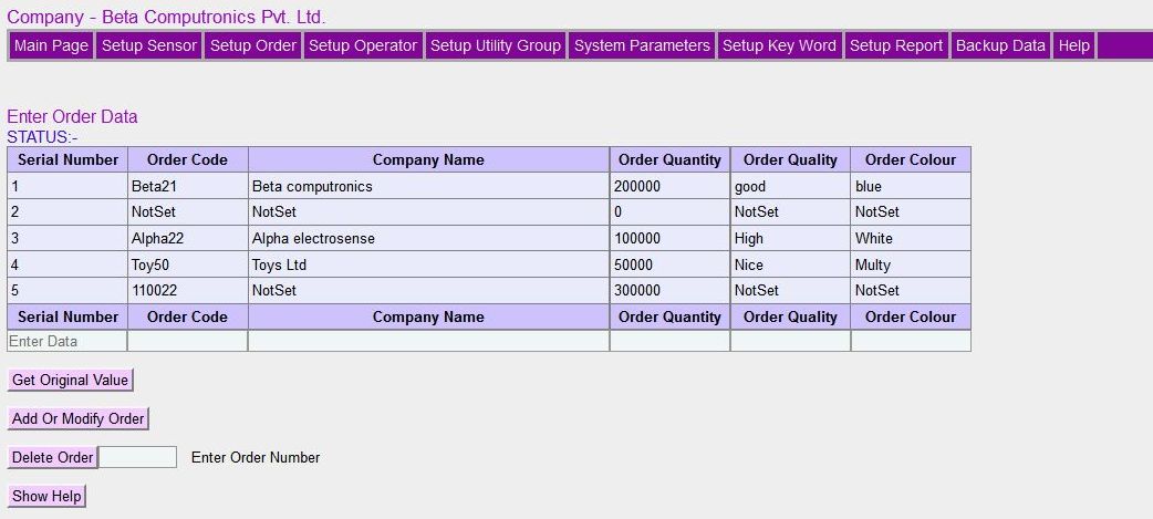
This menu is optional. If you want order management, then enter the data here.
PLEASE READ FOLLOWING BEFORE ENTERING THE DATA.
Please follow limiting values of the data you enter here. If you leave a field blank, default value will be saved. This menu is optional, and can be ignored if you do not want order management.
ORDER CODE. - The order code is a unique and may consist of character or number. The order code can not be repeated.
COMPANY NAME - The company name is from whom order is received.
ORDER QUANTITY - The quantity of order received from company.
ORDER QUALITY. - You can assign a parameter important to the order. The word Quality can also be changed in SETUP KEY WORD menu. This will be displayed on main page, so that it will be easier to identify product easily
ORDER COLOUR. - You can assign a parameter important to the order. The word Colour can also be changed in SETUP KEY WORD menu.
GET ORIGINAL VALUE. - Many time you may need to modify the order data. Enter the order code and click GET ORIGINAL VALUE button, and existing settings will be filled in input boxes. Modify the parameters and click ADD OR MODIFY button and new data will be saved. Please note that you can not modify order code. You will have to delete it completely.
ADD OR MODIFY BUTTON. - When you want to add new order fill up all the text boxes with the data and then press ADD OR MODIFY button. Values outside the specified limit will not be accepted. You can use same button to modify the order data. If you leave a field blank, default value will be saved.
DELETE ORDER. - You can delete an order, by entering order code in text box adjacent to DELETE ORDER button, and by clicking it. You can not delete a running order. You will have to remove the order from ASSIGN ORDER TO MACHINE MENU. When you delete an order, all data associated with order will also be deleted except, old reports. So always be careful, before you delete an order. Take the backup before you delete the order.
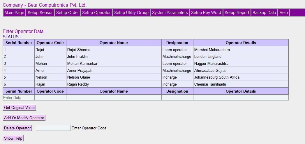
This menu is optional. If you want operator management, then enter the data here.
PLEASE READ FOLLOWING BEFORE ENTERING THE DATA.
Please follow limiting values of the data you enter here. If you leave a field blank, default value will be saved. This menu is optional, and can be ignored if you do not want operator management.
OPERATOR CODE. - This is a unique code to identify the operator. This will appear on all reports. This code must not be repeated. It can have maximum 8 characters or numbers.
OPERATOR NAME. - Full name of operator. This field is not used in processing, so can be left blank.
OPERATOR DESIGNATION. - Operator Designation. This field is not used in processing, so can be left blank.
OPERATOR DETAILS. - The details address or any other information. This field is not used in processing, so can be left blank.
GET ORIGINAL VALUE. - Many time you may need to modify the operator data. Enter the operator code and click GET ORIGINAL VALUE button, and existing settings will be filled in input boxes. Modify the parameters and click ADD OR MODIFY button and new data will be saved. Please note that you can not modify order code. You will have to delete it completely.
ADD OR MODIFY BUTTON. - When you want to add new operator fill up all the text boxes with the data and then press ADD OR MODIFY button. Values outside the specified limit will not be accepted. You can use same button to modify the operator data. If you leave a field blank, default values will be saved.
DELETE OPERATOR. - You can delete an operator, by entering operator code in text box adjacent to DELETE OPERATOR button, and by clicking it. You can not delete a working operator. You will have to remove the operator from ASSIGN OPERATOR TO MACHINE MENU. When you delete an operator, all data associated with operator will also be deleted except, old reports. So always be careful, before you delete an operator. Take the backup before you delete the operator.
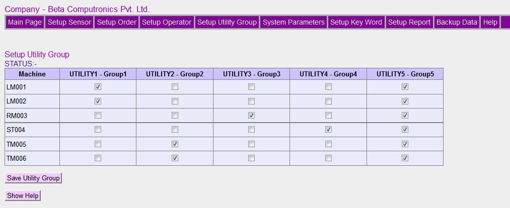
This menu is optional. If you want group and utility reports, then enter the data here.
PLEASE READ FOLLOWING BEFORE ENTERING THE DATA.
If you leave a field blank, that machine will not be included in the group.. This menu is optional, and can be ignored if you do not want to assign Machines to Groups.
GROUP NAMES. - You can group machines according to the machine function. The group names , UTILITY1, UTILITY2, UTILITY3, UTILITY4, UTILITY5 are pre defined and can not be changed. This grouping will help you to examine the data of group of machine for production, efficiency and utility consumption.
UTILITY SENSORS. -You can assign a utility sensor like Kwh meter, water and Air flow meter etc, to a group of machine so that you can get utility consumption of group of machines. For this you will have to name the utility sensor as UTILITY1, UTILITY2, UTILITY3, UTILITY4, UTILITY5.
GROUP FORMATION. -In the above menu just select the machine you want in a particular group by putting a tick mark in the box. Once you have selected groups press Save Utility Group.
UTILITY REPORT. -You can see the group wise data of machines in Utility Report menu.
The system parameters need to be set once. If your system is working perfectly, then you need not change any thing here.
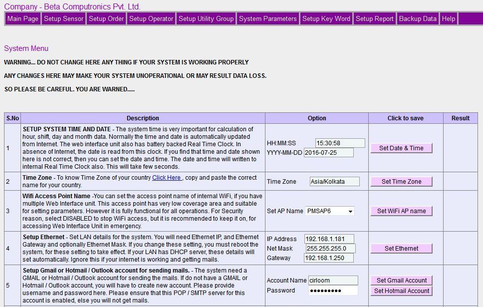
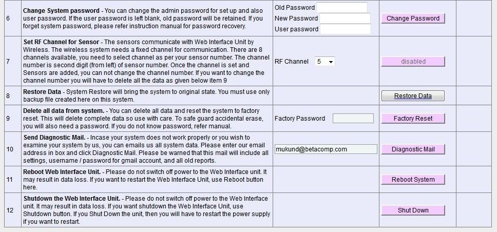
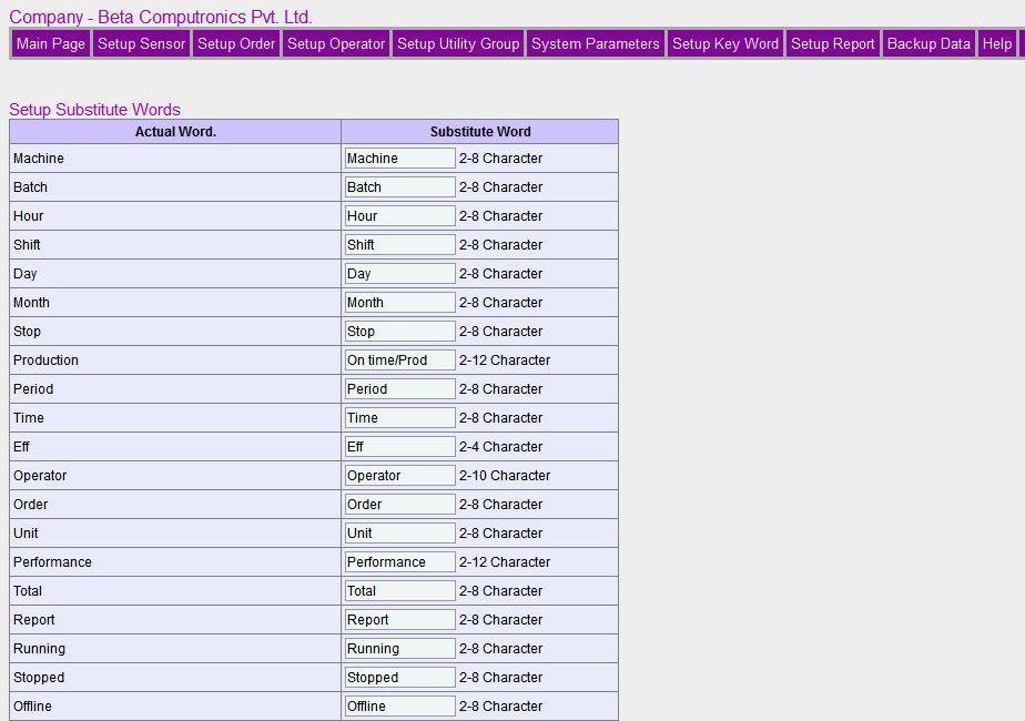
You can replace key words in report with appropriate words. Thus you can have reports in other languages also. However only ASCII characters are only supported.

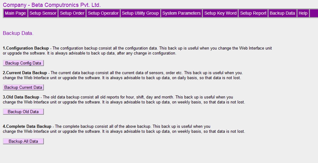
Kindly read the following carefully. The help is provided in menu itself.
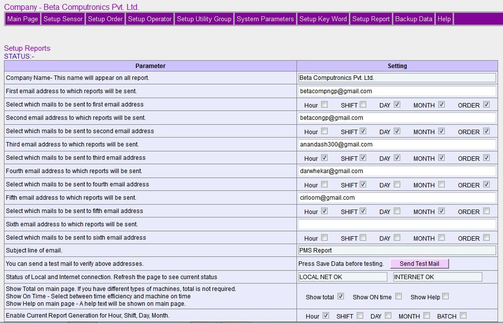

Kindly read the following carefully. The help is provided in menu itself.
The system has two user namely admin and user. The admin can change all the parameter and settings, and user can change few parameters, which are not critical to system. So be very careful, when you log in as admin user. The password for admin and user are provided in manual. These passwords can be changed in system menu, and reset if required.
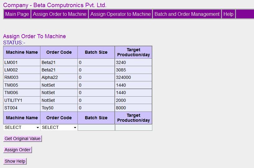
This menu is optional. If you want order management, then enter the data here. You will have to add order in Setup Order menu, before you assign order to machine
PLEASE READ FOLLOWING BEFORE ENTERING THE DATA.
Please follow limiting values of the data you enter here.
This menu is optional, and can be ignored if you do not want to Assign Orders to Machine.
MACHINE NAME. - This is a drop down list to select machine name. The list contains only machine which are added using SETUP SENSOR.
ORDER CODE. - This is a drop down list to select ORDER CODE. The list contains only order which are added using SETUP ORDER.
BATCH SIZE. - You can enter the batch size of order. The order can be breakdown in small batch sizes. You can manage batch size in BATCH AND ORDER MANAGEMENT.
TARGET PRODUCTION. - The target production is used for calculation of machine efficiency. Estimate the per day production, and enter the value here. The efficiency will reflect the machine performance.
GET ORIGINAL VALUE. - Many time you may need to modify the data. Select the machine name and click GET ORIGINAL VALUE button, and existing settings will be filled in input boxes. Modify the parameters and click ASSIGN ORDER button and new data will be saved. Please note that you can not modify order number and machine name.
ASSIGN ORDER. - Once you enter all the values, click ASSIGN ORDER. If all the values are correct, the data will be save and displayed in the list. If you leave a field blank, default value will be saved.
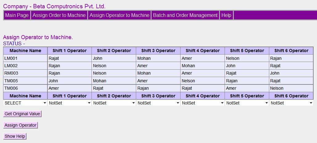
This menu is optional. If you want operator management, then enter the data here. You will have to add operator in Setup Operator menu, before you assign operator to machine
PLEASE READ FOLLOWING BEFORE ENTERING THE DATA.
Please follow limiting values of the data you enter here. If you leave a field blank, default value will be saved. This menu is optional, and can be ignored if you do not want to assign Operator to Machine.
MACHINE NAME. - This is a drop down list to select machine name. The list contains only machine which are added using SETUP SENSOR.
OPERATOR CODE. - This is a drop down list to select OPERATOR CODE. You can assign operator to shift1 to shift 4.The list contains only operator which are added using SETUP OPERATOR.
GET ORIGINAL VALUE. - Many time you may need to modify the data. Select the machine name and click GET ORIGINAL VALUE button, and existing settings will be filled in input boxes. Modify the parameters and click ASSIGN OPERATOR button and new data will be saved. Please note that you can not modify order number and machine name.
ASSIGN OPERATOR. - Once you enter all the values, click ASSIGN OPERATOR, the data will be save and displayed in the list. If you leave a field blank, default value will be saved.
IMPORTANT NOTE. - You can not change the operator name of the current shift. However a grace period of 1 hour is allowed. So if the shift starts at 8.00 AM, you can change the operator name up 9.00 AM for the current shift. After that operator code will be locked.
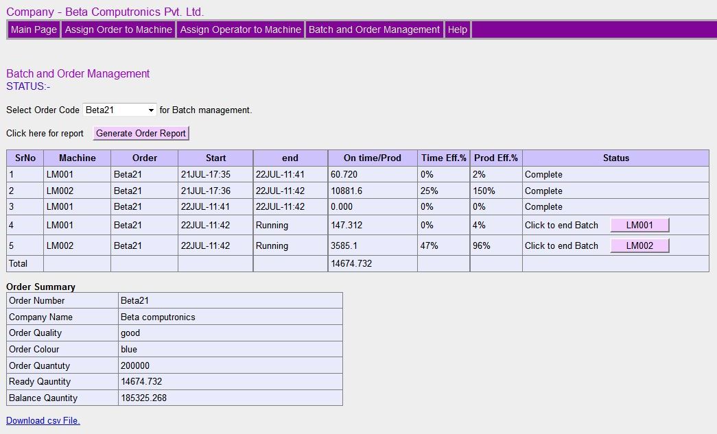
If you have assigned order to machine, then you can make batches. Click the button in last column to finish batch Please note that batch completion is a slow process, and it may take up to a minute to complete.
